Every tech-savvy person is aware that computer processors nowadays consist of countless tiny circuits of great complexity, which allows them to quickly execute complex calculations required in modern computing. Without this, having a palm-size multi-purpose machines like smartphones would be out of the question. However, not many people know how computer hardware required for such a complex tasks is actually designed. The answer will surprise the most: it is programmed, just like software is.
HDL, which stands for Hardware Description Language, is a type of computer language that exists solely for the purpose of designing electronic circuits, although it is similar in structure to an object oriented language. There are even companies that produce and licence HDL instructions required to produce hardware, rather than the hardware itself. A notorious example is ARM, which is behind the design of processors on the most of mobile devices.
Language structure and purpose
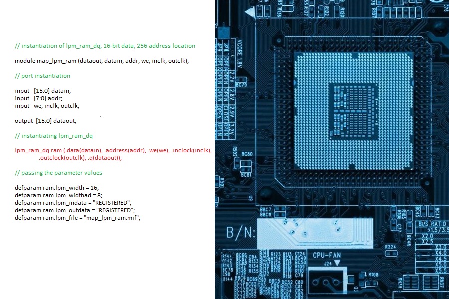
HDL is a language that provides high-level description of functionality of proposed hardware. Complete program can be executed as it is to model the processes in the hardware, or synthesizer tool can be used to translate the code into a visual model of circuit, consisting of primitive components known as netlists, understood by CAD software.
Structurally, HDL is very similar to a programming language that is used in writing software. For example, variables are declared, control flow elements (such as loops) are executed, etc.. However, there are also some very important differences, one of which is explicit notion of “time” that isn’t used in software.
Development process
Coding with HDL is similar to how it is done for software; however the process contains more thorough review stages. This is why it is rare to see computer hardware functioning abnormally, while bugs in software are relatively common.
The code describes inter-relationship between various components of the hardware and, due to the complexity of the hardware, normally needs repeating blocks of code. Therefore software programming languages are often used in conjunction with HDL to produce those.
Synthesis (i.e. conversion into visual diagram) is the final stage of coding, analogous to compiling the software code. Before this stage, HDL code undergoes many stages of automated error checking to see if any circuit components may function abnormally under any known circumstances.
Design validation
Due to impractically large number of possible test cases needed to verify the HDL code against the specifications, the validation process is almost entirely automated with the use of tools such as Property Specification Language. Normally, a tool used in design validation will consist of generator, driver, simulator, monitor and checker, all of which are controlled by arbitration manager.
Generator is the component that generates the input. However, this input needs to be translated before it can be understood by the model, so this is when driver component comes into play. The input is then used by simulator to produce an output based on the current state of the circuit model, as described by HDL. Monitor component records the output result on a score board, which are then checked against the expected results by the checker component. If checker doesn’t find any abnormalities, the code can be synthesized into netlist diagram.
Further resources
This article has only provided high-level summary of HDL. If you are interested in knowing more about it, follow one of the links below: